PricingCase Study
Log in
Case study · Design insight

Turning aerodynamic performance into design insight with AOX

AOX turns sensitivity maps into design direction

Apr 20
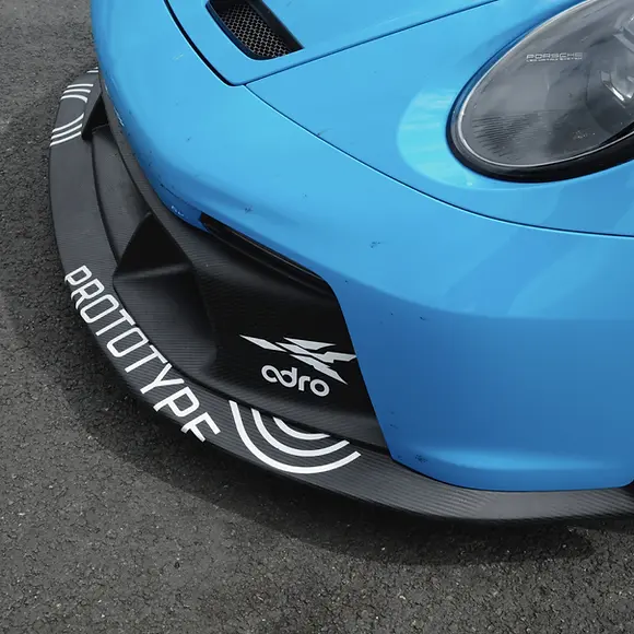
Carbon front splitter on a Porsche 992 GT3
01 / FROM CFD TO DESIGN DIRECTION

Which surfaces to change next

If CFD shows how the current shape performs, AOX helps answer which surfaces to change next and turns that direction into shape candidates designers and engineers can review together.

  1. Input

    Choose editable and protected regions

    Split regions with STL patches or use brush selection directly on the geometry.

  2. Adjoint CFD

    Read the clues in the airflow

    Adjoint CFD computes sensitivity maps for objectives such as drag or downforce, showing which surfaces can change performance.

  3. Shape Optimization

    Turn clues into the next shape candidate

    FFD-style workflows often reduce problem size around control points. AOX takes a different approach, keeping many local surface rules while computing shape updates without explicitly storing a large constraint matrix.

Geometry I/O
Ingest raw STLs, select editable and protected patches, then map the final surface displacement back to the original STL to return optimized STLs.
Shape Model
Represents editable surfaces as small change units and applies regularization and smooth transitions so sensitivity signals do not directly become rough geometry.
Adjoint CFD
Evaluates the current aerodynamic performance, then computes surface directions worth exploring through sensitivity maps for drag or downforce objectives.
Optimization
Computes the next shape update while preserving design rules such as fixed mounting areas, movement limits, and keep-out spaces around nearby parts.
Mesh deformation
Propagates the computed surface change into the volume mesh with p-Laplacian-based deformation, using remesh only when mesh quality breaks down.
02 / ONE REPEATABLE PIPELINE

From setup to optimized STL

AOX connects region selection, objective setup, CFD/Adjoint computation, shape update, mesh deformation, and STL output into one repeatable pipeline.

In simple terms

The user defines which surfaces can change and which must stay fixed. AOX then repeats the process from CFD/Adjoint computation to shape update, mesh deformation, and optimized STL output. The result is not just a sensitivity map, but the next shape candidate ready for design review.

  1. 0

    STL input

    Import the design geometry as STL patches.

  2. 1

    Patch selection

    Separate editable and protected regions.

  3. 2

    Shape setup

    Define surface change units, smoothing behavior, and design rules.

  4. 3

    Mesh generation

    Generate the simulation mesh.

  5. 4

    Flow evaluation

    Evaluate current aerodynamic performance and objective values.

  6. 5

    Adjoint CFD

    Compute drag/downforce sensitivity maps.

  7. 6

    Shape optimization

    Compute the update using both sensitivity and design rules.

  8. 7

    Forward regularization

    Convert rough change signals into smooth surface changes.

  9. 8

    Mesh deformation

    Propagate surface changes into the volume mesh with p-Laplacian. Remesh when needed.

  10. 9

    Optimized STL

    Return a review-ready shape candidate.

A shape must be buildable, not just good-looking

Mounting areas, sealing surfaces, and connection regions can be fixed, while only editable surfaces become targets for shape update. AOX does not apply sensitivity maps directly; it computes the next candidate within design rules that support manufacturing and review.

Simulation must continue as the shape changes

AOX avoids restarting from scratch after every surface change. Instead, p-Laplacian-based mesh deformation helps the volume mesh follow the change. Remeshing is used only when mesh quality breaks down, keeping the simulation loop moving.

Refining the existing shape, not generating random forms

AOX is not topology optimization that creates holes or separates surfaces. It is closer to shape refinement: keeping the existing design structure while adjusting surfaces based on aerodynamic clues.

03 / CFD AND AOX

Connecting CFD results to design decisions

AOX is not a replacement for high-fidelity CFD. Its role is to turn performance information from CFD into direction and shape candidates that help designers decide what to try next.

ItemTypical CFD-centered workflowWhat AOX adds
RoleAnalyzes how the current shape performs and shows problem areas.Connects sensitivity maps and shape updates to suggest which surfaces to change next.
Design rulesOften requires separate adjustment or manual cleanup after simulation.Considers fixed regions, movement limits, and keep-out spaces directly within the shape update.
Difference from FFDFFD-style workflows usually reduce problem size around control points when computing shape updates.AOX keeps many local surface rules while computing shape updates without explicitly storing a large constraint matrix.
OutputPrimarily performance direction or flow analysis results.Returns smooth candidate geometry and optimized STL that can be reviewed in a design process.
User experienceCloser to a workflow configured and interpreted by CFD specialists.Lets designers and engineers make decisions from the same sensitivity maps and candidate shapes.
CASE STUDIES

Keep reading.

  • Previous

    AOX-DRIVEN PERFORMANCE: PORSCHE 992 GT3

    Dec 17

  • Next

    LES VALIDATION: FROM A SPHERE TO THE AHMED BODY

    Oct 2

  • Case studies

    Back to all case studies

LET YOUR NEXT DESIGN TAKE SHAPE

Your next design.
Your move.

Get started

Product

OptimizationDesignGeometryLab

Resources

Case StudyBoard

Service policies

AOX

Aero for everyone.

Phone+82-31-338-1151
Emailsupport@aoxlabs.com
ADRO Inc. · Representative: Seunghyun Yoon · Business Registration No. 827-87-01633
100-29, Songju-ro 236beon-gil, Yangji-myeon, Cheoin-gu, Yongin-si, Gyeonggi-do 17159, Republic of Korea
Copyright © 2026 ADRO Inc. All rights reserved.
AOX

Aero for everyone.

ADRO